
USB or Network Camera: Choose the System Architecture
Compare connection topology, software, power, cabling, latency and maintenance before choosing a camera interface.
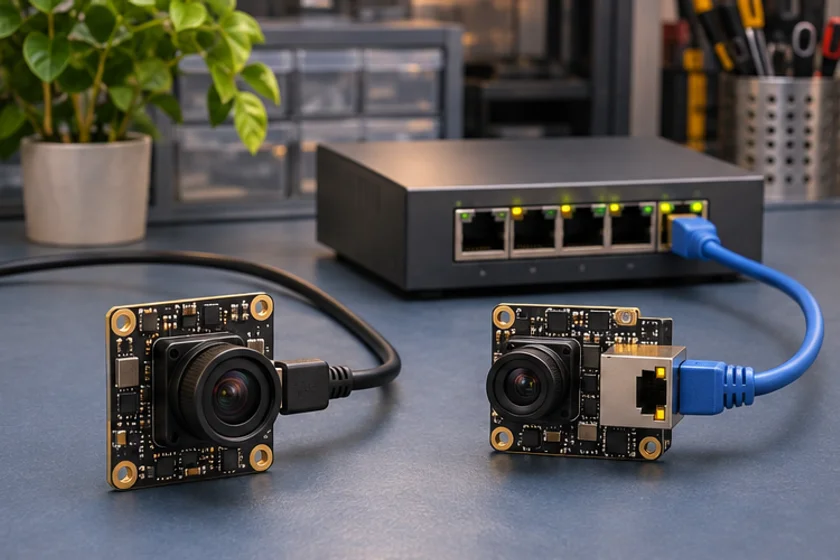
Prepared by Honglan Electronics
Choose between USB and a network camera by reviewing the whole installation. Both can be appropriate, but they imply different connection, software and maintenance decisions. Start with camera locations, host locations, the intended data path and the responsibilities of the equipment team.
Define what “network camera” means
An IP video device used through a streaming protocol is not automatically the same as a GigE Vision industrial camera. Ask which protocols, software interfaces and controls the proposed model supports. An Ethernet connector alone does not establish compatibility with your application.
The same discipline applies to USB. Confirm whether the proposed device uses UVC, another class or a vendor software interface. Basler's interface and installation documentation illustrates that interface selection and software setup belong together. It does not establish capabilities for unrelated products.
Draw the topology
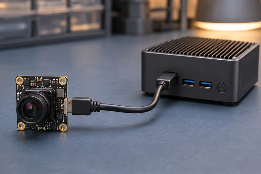
Show each camera, host, hub or switch, cable segment and power source. Include service access and how cables are secured. Record whether the connection is dedicated or shared with other equipment. Describe how the installation expands if another camera is added.
Confirm permitted distances and components for the chosen interface and actual hardware. Do not assume any cable extension, hub or network switch is acceptable merely because the connectors fit. Request evidence for the proposed route and test it under load.
Compare the software path
List the required capture API, image format, timestamps, configuration controls and application framework. Determine how devices are discovered and identified. For network equipment, include address assignment, access control and the recovery procedure after network changes.
Measure end-to-end delay at the point that matters to the equipment. Distinguish exposure timing, transmission, decoding, buffering and application processing. An interface data-rate figure is not a latency specification.
Budget power and operations
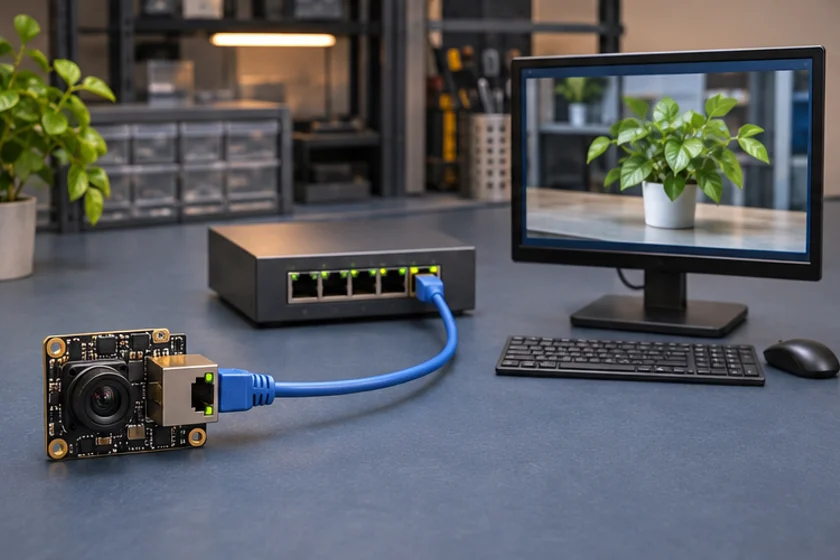
Identify whether power comes from the host, a separate supply or a supported network power arrangement. Confirm the exact model's requirements; network connectivity does not imply Power over Ethernet, and a USB connection does not prove the host can supply every configuration.
Plan for replacement and troubleshooting. A service technician should be able to identify the approved device, inspect the route, restore configuration and verify operation. Keep firmware and configuration backups where the vendor supports them. Avoid a design that depends on undocumented manual settings.
Run a representative comparison
- Build the proposed final topology.
- Select the required capture mode.
- Start the production processing workload.
- Add the expected shared traffic or peripherals.
- Measure continuity and end-to-end delay.
- Test power cycling and connection recovery.
- Document configuration and replacement steps.
Review failures against the original task. A convenient bench setup may be unsuitable for a remote camera position, while a network architecture may add unnecessary administration inside a compact device. The right result depends on your installation, not a universal interface ranking.
Browse products for candidates and send the connection diagram when requesting advice. Ask the supplier to confirm protocols, software integration and power for the exact model, then approve the architecture using captured evidence.
Apply this to a camera module
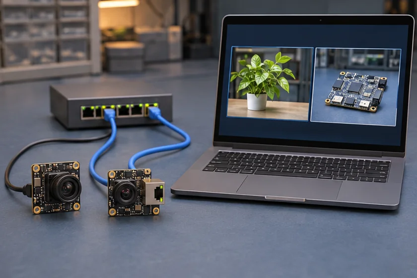
Compare a host-connected IMX415 USB module and the IMX335 RJ45 module to see the difference in cabling and host requirements.
Technical references
- Map host and endpoints
- Compare cable and power
- Check capture and latency
- Test representative loads
Is every Ethernet camera GigE Vision compatible?
No. Confirm the actual protocols, software interfaces and controls for the specific model.
Does a faster interface guarantee lower latency?
No. Exposure, buffering, decoding and application processing also affect the measured end-to-end delay.