
Camera Integration Troubleshooting: Isolate the Failure Layer
Diagnose detection, capture, image and recovery faults with a controlled sequence and reproducible evidence.
Prepared by Honglan Electronics
Diagnose camera integration problems by identifying the first layer that fails. Detection, driver binding, stream negotiation, image content and application processing are separate checkpoints. Changing several parts at once may hide the cause and make a later recurrence harder to solve.
Start with a written symptom
Record what happened, what should have happened and the smallest sequence that reproduces it. Include whether the failure is permanent, intermittent or associated with another action. Note the first observed time and recent changes.
Save the sample identity, firmware, host, operating system, application version, cable and connection topology. A statement such as “the camera disconnects” is incomplete without identifying whether the device disappears, the stream stops or the application simply stops displaying frames.
Check physical detection and power
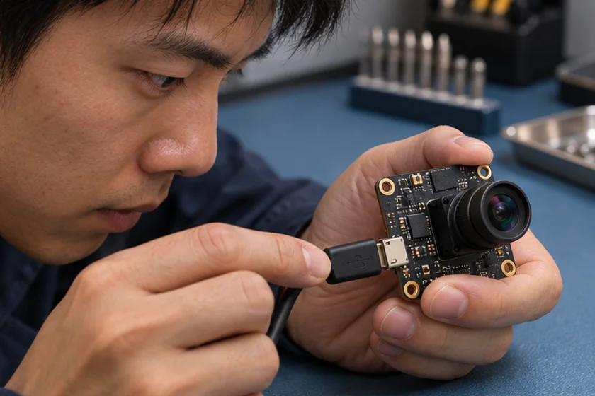
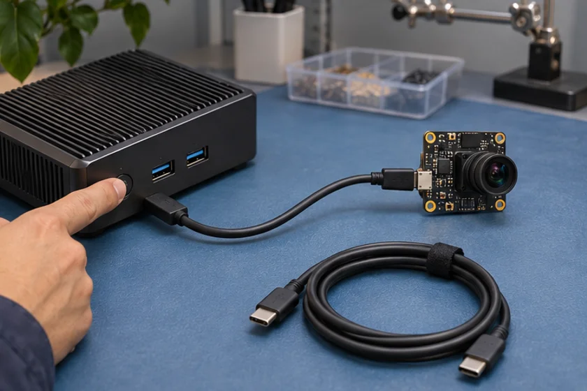
Inspect the approved connectors, cable seating and power arrangement. Use a known-good approved cable and direct connection as a controlled comparison where the installation permits it. Do not improvise pinouts, supply voltages or unsupported adapters.
Review operating-system device information and logs. If the device is not detected, application image settings are unlikely to be the first useful investigation. Record reset or connection errors and determine whether other peripherals share the same failure.
Confirm the driver and reference capture
For a UVC device, verify that the intended class driver is bound. Microsoft documents its supplied driver for compliant devices; a proprietary control utility may involve additional software. Keep ordinary video capture separate from optional vendor-control behaviour.
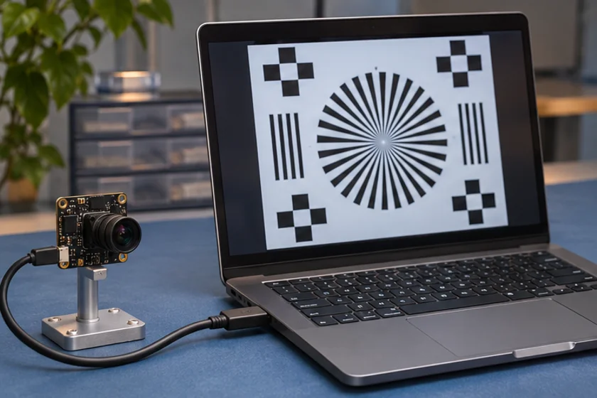
Use a suitable reference capture tool before debugging the full application. Enumerate modes, select the requested combination and read back the actual selection. If a reference tool works, compare your application's format, permissions, buffers and conversion path.
Separate a bad image from a failed stream
For a black or unexpected image, determine whether frames are arriving. Check exposure behaviour, lens obstruction, target illumination and the selected stream. Preserve an original frame instead of relying only on a display screenshot.
For corruption or pauses, record timing and error information. Reduce variables one at a time: capture mode, concurrent workload, connection topology or application processing. Restore the baseline between experiments and label every result.
Reproduce lifecycle failures
If the fault appears after restart, reconnect or suspend, test that transition directly. Define how the application closes resources and finds the intended device again. A successful fresh launch does not prove recovery works after a partial failure.
Run the final test with production peripherals and processing enabled. A problem that disappears in a minimal configuration may still be real; the minimal setup helps identify which added condition triggers it.
Prepare an actionable escalation
Provide the connection diagram, exact mode, logs, reproducible steps, expected result and a short test history. Include reference-tool results and known-good comparisons. Remove sensitive images and credentials before sharing.
State what remains unknown rather than proposing an unsupported cause. If the evidence points to an installation mismatch, resolve it against the actual hardware documentation. Do not apply another manufacturer's model-specific settings blindly.
Use the UVC integration guide to establish the baseline. Contact support with the evidence package so engineering can repeat the failure or identify the next controlled experiment.
Apply this to a camera module
On the IMX415 USB board, test the documented MJPEG and YUY2 modes separately when isolating a format negotiation or frame delivery issue.
Technical references
- Record the symptom
- Check cable and detection
- Isolate capture or image faults
- Reproduce and log recovery
Should I change the camera, cable and software together?
Change one variable at a time where practical so the result identifies a cause rather than merely hiding the failure.
What is the most useful support attachment?
A concise reproduction procedure with hardware and software identities, selected mode, logs and reference-tool results.