
Field of View and Lens Selection for Camera Modules
Specify scene coverage, distance, sensor format and useful edge detail before selecting a lens.
Prepared by Honglan Electronics
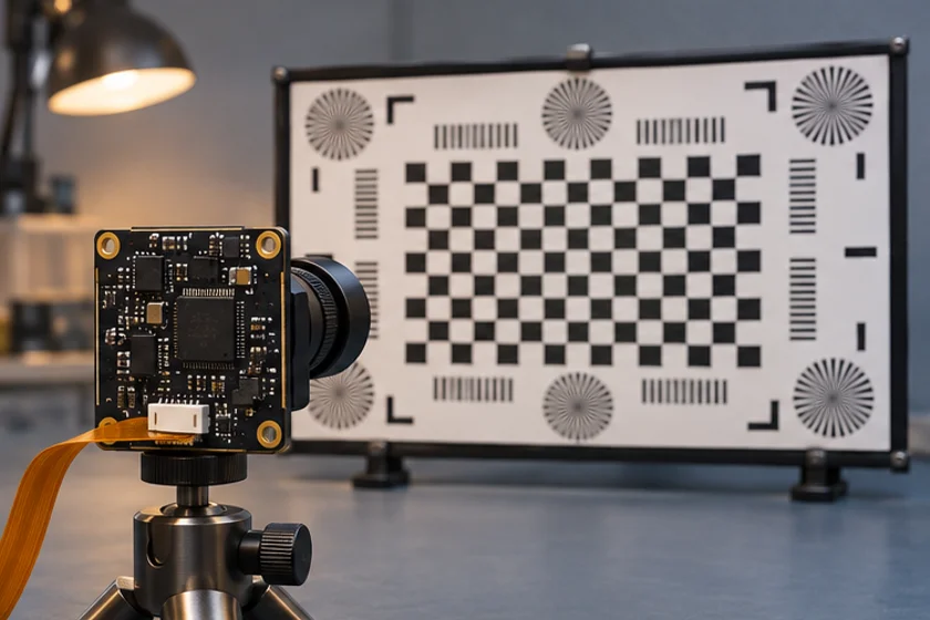
Select a lens by the scene that must fit in the image and the detail that must remain usable. A wide-angle claim alone is insufficient. You need the field-of-view convention, sensor configuration, working distance and a capture showing how the proposed assembly performs across the image.
Specify physical coverage first
Measure the target width and height, then include placement tolerance and any required surrounding area. Record the available distance between the target and the camera assembly. If the target can tilt or vary in height, show those extremes in a drawing.
For many equipment projects, a requirement in millimetres at a working distance is clearer than a requirement in degrees. It connects the optical choice to the mechanical design and gives the sample test a direct pass criterion. Keep the reference point for measuring distance explicit.
Clarify angle and sensor conditions
Ask whether a quoted view angle is horizontal, vertical or diagonal. Confirm the sensor's active output region used for that figure. A crop or a different output mode can change the visible scene even though the lens has not changed.
Edmund Optics explains how focal length, sensor dimensions and working distance relate to coverage. First-order calculations help produce a shortlist, but do not replace the proposed lens data and a physical verification. Lens distortion and mechanical reference points matter when checking an installed assembly.
Check detail where it is needed
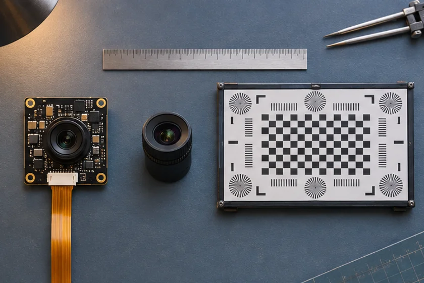
A lens that covers the entire target may still fail at the corners or near a small feature. Place a representative target at several locations in the image. Evaluate the feature size that the equipment actually needs to recognize, rather than relying only on a central image.
Use the intended aperture or fixed optical configuration and the production illumination. Check reflections, vignetting and any obstruction introduced by the housing. A protective window can affect the practical image, so perform final approval with that window present.
Account for distortion and calibration
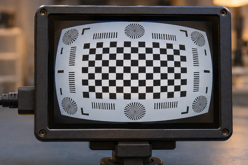
If geometry matters, define the permitted distortion and the calibration procedure. A wide view may be acceptable for observation while requiring more work for measurement. Do not equate nominal pixel dimensions with equal measurement accuracy everywhere in the frame.
Record the chosen resolution and any software correction. Correction can change the remaining coverage or redistribute detail. Keep a raw sample as well as the processed result so engineering can separate optical behaviour from application processing.
Confirm the mechanical assembly
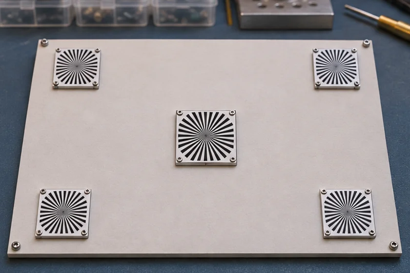
Request the mounting interface, lens protrusion, adjustment access and full envelope drawing. Check clearances against cables, illumination and enclosure openings. Specify whether focus is set before delivery or adjusted during equipment assembly.
For production, identify the exact approved lens rather than describing it only as “wide angle.” Ask for change notification if an alternate lens is proposed. Re-test any substitution against the original coverage and detail criteria.
Approval checklist
Capture the nominal and extreme target positions, verify coverage, evaluate centre and edge detail, inspect enclosure interference and save the settings. Include a marked photograph of the distance measurement and the accepted drawing revision.
Combine these results with focus selection. To discuss an optical option, send your coverage drawing with dimensions, distances and the smallest feature of interest. Treat catalogue angles as shortlist information until the complete assembly is confirmed.
Apply this to a camera module
Use the horizontal and vertical angles on the IMX335 network module to plan coverage, or compare interchangeable optics on the CS-mount USB camera.
Technical references
- Measure required coverage
- Match sensor and lens
- Check edge detail
- Verify fit and calibration
Why can two lenses with the same quoted FOV look different?
The quoted angle may use different axes, sensor regions, distortion conventions or working conditions.
Can a lens calculator replace sample testing?
No. Use it for initial selection, then verify the proposed lens, module, enclosure and target.