
FPC Camera Module Installation: A Mechanical Checklist
Verify connector identity, contact orientation, routing and assembly access before integrating a flexible camera assembly.
Prepared by Honglan Electronics
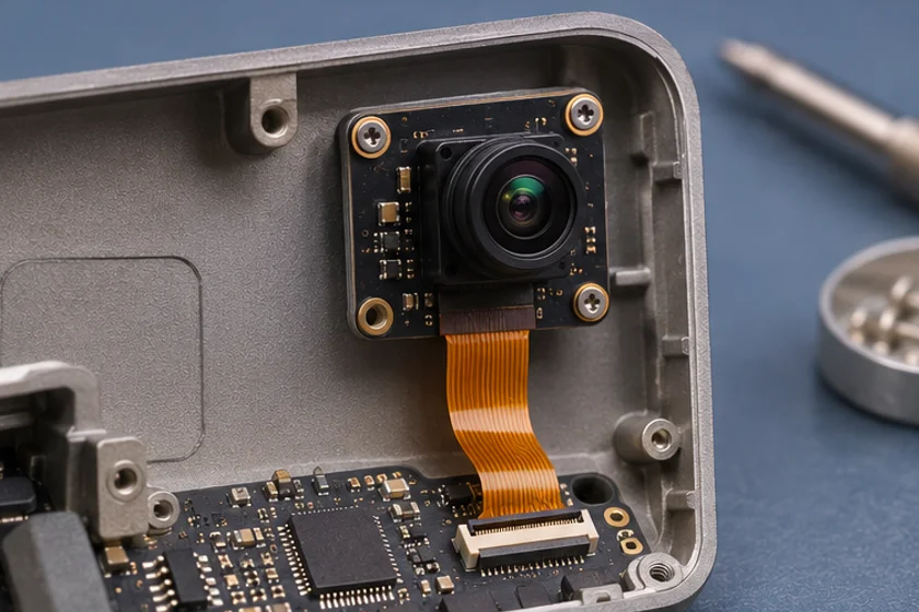
An FPC camera assembly needs a mechanical and electrical integration plan. A flexible section can help fit a camera into a confined enclosure, but it does not make connector orientation, routing or strain irrelevant. Approve the complete assembly drawing and the actual connector instructions before installation.
Identify the exact connection
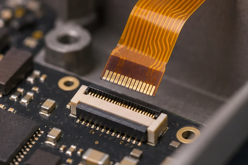
Obtain the connector manufacturer and part number, mating-flex drawing, contact side, pin count, pitch and permitted flex thickness. Similar-looking connectors are not automatically interchangeable. Confirm the signal pinout and supply requirements from the actual module documentation.
Do not connect an unknown cable to test whether it works. A matching outline does not prove electrical compatibility. If the drawing and sample differ, stop that assembly step and ask engineering to resolve the discrepancy before power is applied.
Follow the specific actuator procedure
Connector latches and insertion methods vary. Hirose publishes connector-family-specific handling guidance, including instructions for particular actuator arrangements. Apply only the instructions for the exact installed connector. Do not transfer insertion angles, force values or latch movements from another series.
Provide enough access for the operator to insert the flex correctly and inspect the result. A design that is easy to assemble before the enclosure is closed may become difficult when adjacent parts are installed. Include the actual assembly sequence in the review.
Plan the flex route
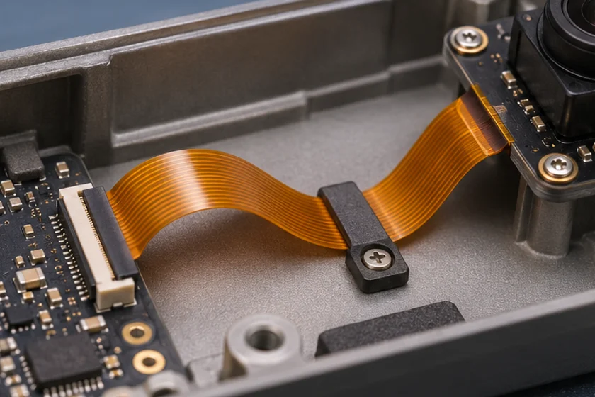
Mark bends, supports, potential pinch points and the moving parts near the route. Obtain bend limits and any dynamic-flex conditions from the flex and assembly supplier. There is no single safe bend radius for every FPC construction.
Avoid using the connector as the anchor for cable loads. Define the intended strain relief with engineering and verify that closing the enclosure does not pull, twist or sharply crease the assembly. Include tolerance in the route so a nominally correct drawing remains buildable.
Keep optics and electronics protected
Use an appropriate electrostatic-discharge handling process and keep exposed optics clean according to the supplier's instructions. Do not press on the lens holder or sensor area to seat a connector. Record when protective films are removed and how the assembly is inspected afterward.
Check board standoffs, screw lengths and nearby conductive surfaces. A mounting point should match the approved drawing. Do not drill, trim or force the assembly to resolve an unexpected interference without a design review.
Validate an installed sample
Before closing the housing, inspect seating and continuity using the approved procedure. Then verify enumeration, the intended video mode and image orientation. Repeat the video test after the enclosure is closed to catch routing or mechanical effects.
Document the assembly with clear photographs. If movement is part of normal operation, create a representative cycle test with agreed limits. Record what was tested instead of assuming that a flexible cable is suitable for repeated motion.
Information to send for a custom fit
Provide the enclosure model, camera position, connector access, route length, movement, target view and assembly sequence. Include drawings rather than relying on a requested flex length alone. Review the customization requirements guide and contact engineering before committing to a layout.
Treat a successful bench connection as an early check. Final approval should cover the installed optical result, reliable electrical operation and a repeatable assembly method for the chosen revision.
Apply this to a camera module
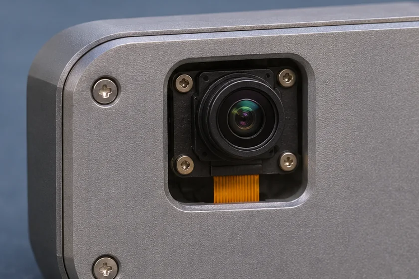
Compare the QF58 flex camera drawing with the DH-5835F main-board layout before setting enclosure clearances.
Technical references
- Identify flex and connector
- Verify contact orientation
- Route the flex without strain
- Test in the final housing
Do all similar FPC connectors use the same insertion method?
No. Identify the exact connector and follow its manufacturer's drawing and handling instructions.
What bend radius should I use?
Obtain it for the specific flex construction and operating conditions; there is no universal value.